Instructions -
The main screen consists of two parts; the Main scenario and the Topology tabs. The main scenario describes TSHOOT.com test bed. The Topology tabs allow you to display the appropriate and select the trouble ticket.
To complete the item, you will first need to familiarize yourself with the TSHOOT.com test bed by clicking on the master scenario first and then the topologies tabs.
Once you are familiar with the test bed and the topologies, you should start evaluating the trouble ticket. You will be presented with a Trouble Ticket scenario that will describe the fault condition. You will need to determine on which device the fault condition is located, to which technology the fault condition is related, and the solution to each trouble ticket. This will be done by answering three questions.
Ticket Selection -
✑ To begin, click on the Ticket on the Topology tabs.
Some of the questions will require you to use the scroll bar to see all options.
✑ Please note.
Fault Isolation -
✑ Read the ticket scenario to understand the fault condition.
✑ Open the appropriate topology, based upon the ticket scenario.
✑ Open the console of the desired device by clicking on that device in the topology, based upon your troubleshooting methodology.
✑ Use the supported show, ping and trace commands to begin your fault isolation process.
✑ Move to other devices as need by clicking on those devices within the topology.
Fault Identification -
✑ The trouble ticket will include three questions that you will need to answer:
1. Which device contains the fault
2. Which technology the fault condition is related to
3. What is the solution to the issue
✑ To advance to the next question within the ticket click on "Next Question".
✑ When you click "DONE", the trouble ticket will turn RED and will no longer be accessible.
✑ You may also use the "Previous Question" button to review questions within that specific ticket.
✑ To complete a trouble ticket, answer all three questions and click "DONE". This will store your response to the questions. Do not click on "DONE" unless you have answered all questions within the ticket.
Item Completion -
✑ Click the NEXT button on the bottom of the screen once a ticket is RED. This action moves you to the next item.
Scenario -
The company has created the test bed network shown in the layer 2 and layer 3 topology exhibits.
This network consists of four routers, two layer 3 switches and two layer 2 switches.
In the IPv4 layer 3 topology, R1, R2, R3, and R4 are running OSPF with an OSPF process number 1.
DSW1, DSW2 and R4 are running EIGRP with an AS of 10. Redistribution is enabled where necessary.
R1 is running a BGP AS with a number of 65001. This AS has an eBGP connection to AS 65002 in the ISP's network. Because the company's address space is in the private range, R1 is also providing NAT translations between the inside (10.1.0.0/16 & 10.2.0.0/16) networks and the outside (209.65.200.0/24) network.
ASW1 and ASW2 are layer 2 switches.
NTP is enabled on all devices with 209.65.200.226 serving as the master clock source.
The client workstations receive their IP address and default gateway via R4's DHCP server. The default gateway address of 10.2.1.254 is the IP address of HSRP group 10 which is running on DSW1 and DSW2.
In the IPv6 layer 3 topology R1, R2, and R3 are running OSPFv3 with an OSPF process number 6. DSW1, DSW2 and R4 are running RIPng process name
RIP_ZONE. The two IPv6 routing domains, OSPF 6 and RIPng are connected via GRE tunnel running over the underlying IPv4 OSPF domain. Redistribution is enabled where necessary.
Recently the implementation group has been using the test bed to do a "˜proof-of-concept' on several implementations. This involved changing the configuration on one or more of the devices. You will be presented with a series of trouble tickets related to issues introduced during these configurations.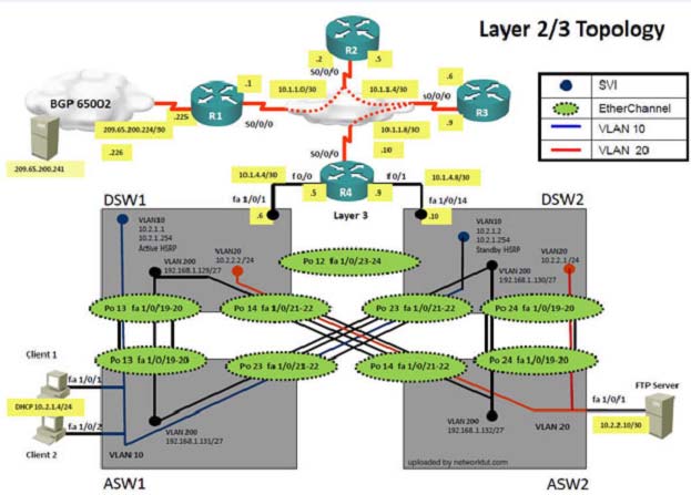
The implementation group has been using the test bed to do a "˜proof-of-concept' that requires both Client 1 and Client 2 to access the WEB Server at
209.65.200.241. After several changes to the network addressing, routing scheme, DHCP services, NTP services, and FHRP services, a trouble ticket has been opened indicating that Client 1 cannot ping the 209.65.200.241 address.
Use the supported commands to isolate the cause of this fault and answer the following questions.
What is the solution to the fault condition?

Fiss
5 years, 7 months ago