What is the maximum number of switches that can be stacked using Cisco StackWise?
Correct Answer:
D
🗳️
Up to 9 Cisco Catalyst switches can be stacked together to build single logical StackWise switch since Cisco IOS XE Release 3.3.0SE. Prior to Cisco IOS XE
Release3.3.0SE, up to 4 Cisco Catalyst switches could be stacked together.
Reference: http://www.cisco.com/c/en/us/products/collateral/switches/catalyst-3850-series-switches/qa_c67-722110.html
A network engineer wants to add a new switch to an existing switch stack. Which configuration must be added to the new switch before it can be added to the switch stack?
Correct Answer:
A
🗳️
Switch Stack Offline Configuration
(to supply a configuration to) a new switch before it joins the switch stack. You can configure in advance the stack member number, the switch type, and the interfaces associated with a switch that is not currently part of the stack. The configuration that you create on
.
global configuration command. The provisioned
configuration is automatically created when a switch is added to a switch stack and when no provisioned configuration exists.
When you configure the interfaces associated with a provisioned switch (for example, as part of a VLAN), the switch stack accepts the configuration, and the information appears in the running configuration. The interface associated with the provisioned switch is not active, operates as if it is administratively shut down, and the no shutdown interface configuration command does not return it to active service. The interface associated with the provisioned switch does not appear in the display of the specific feature; for example, it does not appear in the show vlan user EXEC command output.
The switch stack retains the provisioned configuration in the running configuration whether or not the provisioned switch is part of the stack. You can save the provisioned configuration to the startup configuration file by entering the copy running-config startup-config privileged EXEC command. The startup configuration file ensures that the switch stack can reload and can use the saved information whether or not the provisioned switch is part of the switch stack.
Effects of Adding a Provisioned Switch to a Switch Stack
When you add a provisioned switch to the switch stack, the stack applies either the provisioned configuration or the default configuration.
Table 5-1 -
lists the events
that occur when the switch stack compares the provisioned configuration with the provisioned switch.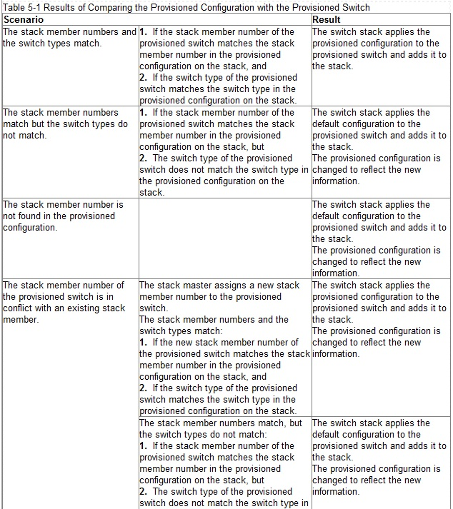
Reference: http://www.cisco.com/c/en/us/td/docs/switches/lan/catalyst3750x_3560x/software/release/12-2_55_se/configuration/guide/3750xscg/swstack.html
What percentage of bandwidth is reduced when a stack cable is broken?
Correct Answer:
C
🗳️
Physical Sequential Linkage -
The switches are physically connected sequentially, as shown in Figure 3. A break in any one of the cables will result in the stack bandwidth being reduced to half of its full capacity. Subsecond timing mechanisms detect traffic problems and immediately institute failover. This mechanism restores dual path flow when the timing mechanisms detect renewed activity on the cable.
Cisco StackWise Technology Resilient Cabling
Figure 3.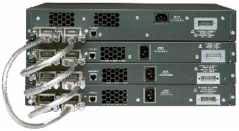
Reference: http://www.cisco.com/c/en/us/products/collateral/switches/catalyst-3750-series-switches/prod_white_paper09186a00801b096a.html
Refer to the exhibit.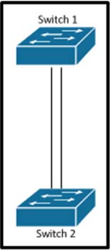
Which set of configurations will result in all ports on both switches successfully bundling into an EtherChannel?
Correct Answer:
D
🗳️
The different etherchannel modes are described in the table below: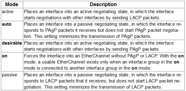
Both the auto and desirable PAgP modes allow interfaces to negotiate with partner interfaces to determine if they can form an EtherChannel based on criteria such as interface speed and, for Layer 2 EtherChannels, trunking state and VLAN numbers.
Interfaces can form an EtherChannel when they are in different PAgP modes as long as the modes are compatible. For example:
✑ An interface in the desirable mode can form an EtherChannel with another interface that is in the desirable or auto mode.
✑ An interface in the auto mode can form an EtherChannel with another interface in the desirable mode.
An interface in the auto mode cannot form an EtherChannel with another interface that is also in the auto mode because neither interface starts PAgP negotiation.
An interface in the on mode that is added to a port channel is forced to have the same characteristics as the already existing on mode interfaces in the channel.
Reference: http://www.cisco.com/c/en/us/td/docs/switches/lan/catalyst3550/software/release/12-1_13_ea1/configuration/guide/3550scg/swethchl.html
Refer to the exhibit.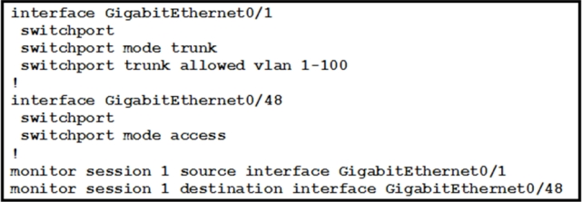
How can the traffic that is mirrored out the GigabitEthernet0/48 port be limited to only traffic that is received or transmitted in VLAN 10 on the GigabitEthernet0/1 port?
Correct Answer:
C
🗳️
To start a new flow-based SPAN (FSPAN) session or flow-based RSPAN (FRSPAN) source or destination session, or to limit (filter) SPAN source traffic to specific
VLANs, use the monitor session filter global configuration command.
Usage Guidelines -
You can set a combined maximum of two local SPAN sessions and RSPAN source sessions. You can have a total of 66 SPAN and RSPAN sessions on a switch or switch stack.
You can monitor traffic on a single VLAN or on a series or range of ports or VLANs. You select a series or range of VLANs by using the [ , | -] options.
If you specify a series of VLANs, you must enter a space before and after the comma. If you specify a range of VLANs, you must enter a space before and after the hyphen ( -).
VLAN filtering refers to analyzing network traffic on a selected set of VLANs on trunk source ports. By default, all VLANs are monitored on trunk source ports. You can use the monitor session session_number filter vlan vlan-id command to limit SPAN traffic on trunk source ports to only the specified VLANs.
VLAN monitoring and VLAN filtering are mutually exclusive. If a VLAN is a source, VLAN filtering cannot be enabled. If VLAN filtering is configured, a VLAN cannot become a source.
Reference: http://www.cisco.com/c/en/us/td/docs/switches/lan/catalyst3850/software/release/3se/network_management/command_reference/b_nm_3se_3850_cr/ b_nm_3se_3850_cr_chapter_010.html#wp3875419997
Refer to the exhibit.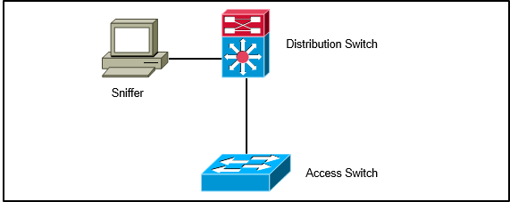
A network engineer wants to analyze all incoming and outgoing packets for an interface that is connected to an access switch. Which three items must be configured to mirror traffic to a packet sniffer that is connected to the distribution switch? (Choose three.)
Correct Answer:
BCD
🗳️
You can analyze network traffic passing through ports or VLANs by using SPAN or RSPAN to send a copy of the traffic to another port on the switch or on another switch that has been connected to a network analyzer or other monitoring or security device. SPAN copies (or mirrors) traffic received or sent (or both) on source ports or source VLANs to a destination port for analysis.
RSPAN supports source ports, source VLANs, and destination ports on different switches (or different switch stacks), enabling remote monitoring of multiple switches across your network. The traffic for each RSPAN session is carried over a user-specified RSPAN VLAN that is dedicated for that RSPAN session in all participating switches. The RSPAN traffic from the source ports or VLANs is copied into the RSPAN VLAN and forwarded over trunk ports carrying the RSPAN
VLAN to a destination session monitoring the RSPAN VLAN. Each RSPAN source switch must have either ports or VLANs as RSPAN sources. The destination is always a physical port.
Reference: http://www.cisco.com/c/en/us/td/docs/switches/lan/catalyst3750x_3560x/software/release/12-2_55_se/configuration/guide/3750xscg/swspan.html
After an EtherChannel is configured between two Cisco switches, interface port channel 1 is in the down/down state. Switch A is configured with channel-group 1 mode active, while Switch B is configured with channel-group 1 mode desirable. Why is the EtherChannel bundle not working?
Correct Answer:
A
🗳️
Here we have a situation where one switch is using active mode, which is an LACP mode, and the other is using desirable, which is a PAGP mode. You can not mix the LACP and PAGP protocols to form an etherchannel. Here is a summary of the various etherchannel modes: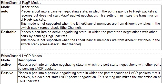
Reference: http://www.cisco.com/c/en/us/td/docs/switches/lan/catalyst2960/software/release/12-2_55_se/configuration/guide/scg_2960/swethchl.html
An EtherChannel bundle has been established between a Cisco switch and a corporate web server. The network administrator noticed that only one of the
EtherChannel links is being utilized to reach the web server. What should be done on the Cisco switch to allow for better EtherChannel utilization to the corporate web server?
Correct Answer:
E
🗳️
EtherChannel load balancing can use MAC addresses, IP addresses, or Layer 4 port numbers, and either source mode, destination mode, or both. The mode you select applies to all EtherChannels that you configure on the switch. Use the option that provides the greatest variety in your configuration. For example, if the traffic on a channel only goes to a single MAC address (which is the case in this example, since all traffic is going to the same web server), use of the destination
MAC address results in the choice of the same link in the channel each time. Use of source addresses or IP addresses can result in a better load balance.
Reference: http://www.cisco.com/c/en/us/support/docs/lan-switching/etherchannel/12023-4.html
Interface FastEthernet0/1 is configured as a trunk interface that allows all VLANs. This command is configured globally: monitor session 2 filter vlan 1 8, 39, 52
What is the result of the implemented command?
Correct Answer:
E
🗳️
The "monitor session filter" command is used to specify which VLANS are to be port mirrored using SPAN. This example shows how to monitor VLANs 1 through 5 and VLAN 9 when the SPAN source is a trunk interface:
Switch(config)# monitor session 2 filter vlan 1 5 , 9
Reference: http://www.cisco.com/c/en/us/td/docs/switches/lan/catalyst4500/12-2/25ew/configuration/guide/conf/span.html/index.html#wp1066836
A network engineer notices inconsistent Cisco Discovery Protocol neighbors according to the diagram that is provided. The engineer notices only a single neighbor that uses Cisco Discovery Protocol, but it has several routing neighbor relationships. What would cause the output to show only the single neighbor?
Correct Answer:
A
🗳️
If all of the routers are connected to each other using a layer 2 switch, then each router will only have the single switch port that it connects to as its neighbor.
Even though multiple routing neighbors can be formed over a layer 2 network, only the physical port that it connects to will be seen as a CDP neighbor. CDP can be used to determine the physical topology, but not necessarily the logical topology.
By buying Contributor Access for yourself, you will gain the following features: